|
This page was exported from The Vespa Guide
[ http://vespaguide.com ] Export date: Mon Jul 14 20:35:07 2025 / +0000 GMT |
Vespa Large Frame - Engine Casing Split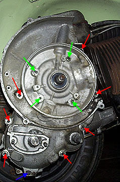 Original Article Posted on scooterhelp.com Engine Casing Split Splitting the casings allows access to the crank, the oil seals, main bearings, and transmission components. There are only a few specialized tools required to do this on a P series engine, although older engines also require a heat source like a propane torch to help split the casings.
The casings can be split in the bike which can be very handy if you are simply replacing a shift cross or gear. To start you need to:
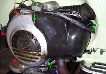
From this point your engine should look like below. We just bought this bike so I have no idea what the little box is next to the carb box. I am guessing we'll bin it and solve the electrical problem without it. It may be an AC regulator??!
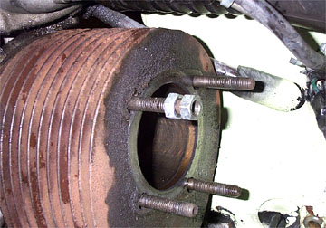
Remove the cylinder head with a 13mm socket and pull it off the studs. The cool thing about splitting Vespa casings is that you don't really have to mess too much with the top end. What is important is to remove the two flywheel side barrel studs so that the barrel will stay in place but allow the casing half to be removed. This means you don't have to mess around with removing the barrel, refitting the piston, compressing the rings, etc.. There is also a small locating stud on the bottom of the barrel which keys into the flywheel side casing which we'll get to a little later on. To remove the studs while in place, use the lock nut trick. Take two 13mm nuts and thread them onto one of the two studs furthest away from the bike.
Then take either two 13mm wrenches or a single 13mm wrench and a 13mm socket (as shown below) and tighten the nuts against each other 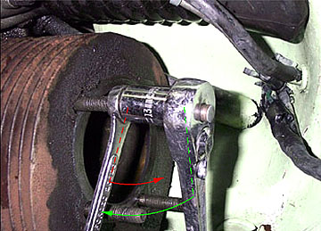 Once tight, loosen the upper nut and the stud should turn and unscrew from the casing. Leave the two nuts on the stud as they can be used to reinstall it when you are done with the engine work.  Once both flywheel side casing studs have been removed the barrel must slide up about 1/4 of an inch to allow a small locating stud in the barrel to dislocate from the casing as shown below with the red arrow - This picture was taken before the barrel studs were removed (by mistake) and the barrel stud is shown with the green arrow to avoid confusion. The gear selector box must also be removed before the casings are split. It is bolted on to the flywheel side casing with two 11mm nuts. Loosen these nuts, remove the lock nuts and washers, and store them in a safe place. Grab the gear selector handgrip on the headset and turn it as far towards 4th gear as possible. This should pop the selector off the casing and is handy because you don't have to mess with the disconnecting the control cables as shown below. 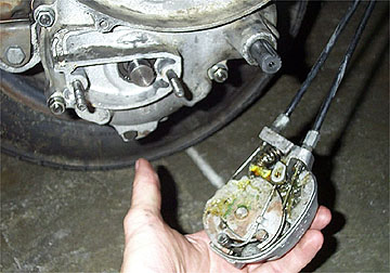 All the crankcase bolts can now be released. Both the flywheel and stator plate must be removed to get to the crankcase bolts around the main crank. Click here for the flywheel removal page. The next step is to use an 11mm socket to loosen all the casing bolts. The ends of the casing bolts that pass through the engine are D shaped so they should not rotate. All these are arrowed below in red. The only casing bolts that have inaccessible ends are the ones directly around the crank, arrowed in green. The final type of bolt is a through bolt that goes the opposite direction than all the others, arrowed in blue. This should be the moment of truth. Refit the kick start and tighten it down - it makes a handy thing to pull on. I usually start by placing one hand behind the flywheel air scoop just below the carb box, and the other on the kick start. You shouldn't have to pull very hard to get things moving and once the casing has cleared the crankshaft it can be removed completely.  You may find that a single spring and a kickstart gear will fall out of the engine when the casings are split and this is completely normal. Once we put this back together again I'll post a page showing where they are supposed to go. Now the casings should be apart and you are ready to replace bearings, replace the shift cross or gears, fit a new casing gasket, replace the kick start rubbers, etc.. 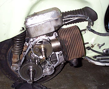
|
|
Post date: 2014-10-10 08:19:35 Post date GMT: 2014-10-10 08:19:35 Post modified date: 2014-10-10 08:19:35 Post modified date GMT: 2014-10-10 08:19:35 |
| Powered by [ Universal Post Manager ] plugin. HTML saving format developed by gVectors Team www.gVectors.com |